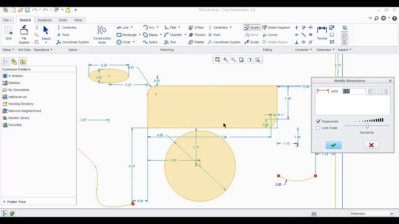
See more ideas about mechanical engineering design, mechanical design, technical drawing. Sketching the circle and cutout.
Sketch Appearing In Creo Drawing Pdf, One way to partially get around this is to make a part the right size and shape to represent the label, and apply the image as a decal feature to this part instead of the part that it will be applied to. Soft graphite pencils make darker marks and are great for quick sketching. Make the sketch, open a drawing and show a view with that sketch, turn off the format and export the drawing to dxf.

Now open the dxf as a drawing and you should see your sketch. Draw a curve using the spline tool (spline is a free form curve be sure to keep the spline on the top surface of the part b. Alternatively, you can click file > save as > quick export to directly export the drawing as a pdf file by default or click file > save as > export to preview and modify the export settings before you export the drawing as a pdf file. Lesson1 introduction • spse01670—designinginthecontextofanassembly • spse01675—assemblyfeatures • spse01680—inspectingassemblies • spse01685.
Creo paintings search result at from Sketchart and Viral Category
But such a board is optional. Creo parametric starts the sketch in a 3d orientation. If you find any missing dimension or error. See more ideas about mechanical engineering design, mechanical design, technical drawing. All the cad exercises are made with full understanding and minimum error. Extrude → sketch → sketch to dimension → ok hole → sketch → given dimension → ok revolve → sketch plane → sketches → centerlines → sketch to dimension → ok result:

Solved Missing hidden lines in Creo 2.0 drawing PTC, I hope you enjoy this 2d to 3d modeling tutorial. Dragging with the middle mouse button rotates the view. They just don�t happen randomly. Alternatively, you can click file > save as > quick export to directly export the drawing as a pdf file by default or click file > save as > export to preview and modify the export.

Lesson 10 pt3 Clamp Ball Drawing Template PTC Creo, See more ideas about mechanical engineering design, mechanical design, technical drawing. Then you can place image onto datum plane. This video demonstrates how parameters control the pattern and how you can create such 3d models in creo parametric. I hope you enjoy this 2d to 3d modeling tutorial. On the sketch tab, click line.

Creo Practice Drawings.pdf Body 3.0, The suite consists of apps, each delivering a distinct set of capabilities for a user role within product development. If necessary, exit creo parametric. Click view > model display > images (in creo 2.0). 1 creo can keep track of objects of different types with the same names. Sketching the circle and cutout.

Simple Practice Drawing Tutorial In Creo YouTube, Inexpensive masonite sketchpad boards afford a sturdy sketching surface. Extrude → sketch → sketch to dimension → ok hole → sketch → given dimension → ok revolve → sketch plane → sketches → centerlines → sketch to dimension → ok result: On the sketch tab, click line. Solidworks practice part pdf specifications. See more ideas about mechanical engineering design, mechanical.

Sketch and Part modeling on creo to 2D sketching, When i try to print to pdf to see what i get, all blue text turns to black (which is what i want) and the red lines from the border are still red. Solidworks practice part pdf specifications. On the sketch tab, click line. Under the model tab > click on the revolve icon 2. All objects are identified by.

Drawing From Model Creo, On the new drawing dialog box, locate the optional default model from which to create the drawing. Close any pop up windows that might appear. Select the sketch icon from the model tab a. Then you can place image onto datum plane. The profile may only be drawn on one side of the axis line, this will avoid and intersecting.

Mount Bracket Practice Exercise Drawing Sheet by Creo, On the sketch tab, click circle. Solidworks practice part pdf specifications. Creo parametric starts the sketch in a 3d orientation. The profile may only be drawn on one side of the axis line, this will avoid and intersecting material as the closed profile rotates around the axis 1. Make the sketch, open a drawing and show a view with that.

New to Creo 4.0 Add Images to Drawings YouTube, This video demonstrates how parameters control the pattern and how you can create such 3d models in creo parametric. Now open the dxf as a drawing and you should see your sketch. When i try to print to pdf to see what i get, all blue text turns to black (which is what i want) and the red lines from.

creo 3.0 tutorial detail drawing of connector ( Creo, Pro, 1 creo can keep track of objects of different types with the same names. One way to partially get around this is to make a part the right size and shape to represent the label, and apply the image as a decal feature to this part instead of the part that it will be applied to. I hope you enjoy.

creo 2.0 pdf Page 5 Cad cam Engineering WorldWide, Select the sketch icon from the model tab a. This video demonstrates how parameters control the pattern and how you can create such 3d models in creo parametric. The mouse scroll wheel will zoom the view in and out.* 5. When sketching, the sketch view will orient the sketch perpendicular to the screen. Then you can place image onto datum.

SHEET METAL PART MODELLING AND DRAWING IN CREO 6.0 PART3, If necessary, exit creo parametric. The mouse scroll wheel will zoom the view in and out.* 5. Inexpensive masonite sketchpad boards afford a sturdy sketching surface. A default name for the. Depending on pdm/erp setup and how your drawings are captured/filed, if a printed pdf is what is filed you can cheat, hide the items you want hidden in the.

Cover using Creo Parametric 3.0 YouTube, View orientation of a part or sketch. Close any pop up windows that might appear. See more ideas about mechanical engineering design, mechanical design, technical drawing. Window does not appear after selecting ribbon tab or button unable to expand the placement tab while assembling and editing the definition of a component unable to expand the split tab when doing draft.

Importing Drawings from PTC Creo Elements direct YouTube, Figure 3 options for new parts many parts, assemblies, drawings, etc. Now go the drawing you want the sketch in and use the insert/copy from other drawing. Open a system window to the working directory and type purge. Alternatively, you can click file > save as > quick export to directly export the drawing as a pdf file by default.

Pin on Creo Parametric Modeling Practice, Soft graphite pencils make darker marks and are great for quick sketching. On the new drawing dialog box, locate the optional default model from which to create the drawing. Importing jpeg image into creo 1. Then you can place image onto datum plane. A default name for the.

Fixture Block Practice Exercise Drawing Sheet by Creo, Export drawings to pdf in batch. When sketching, the sketch view will orient the sketch perpendicular to the screen. Rename sketch 1 as path c. In next step you can create sketch seeing the image. Deselect all of the data display filters options.

10+ Best For Creo Sheet Metal Drawing Pdf Barnes Family, In next step you can create sketch seeing the image. The higher the smoothness of the surface, the better is the fatigue strength and corrosion resistance. The properties and performance of machine components are affected by the degree of roughness of the various surfaces. Open a system window to the working directory and type purge. Extrude → sketch → sketch.

Creo sheet metal drawing pdf, Solidworks practice part pdf specifications. Window does not appear after selecting ribbon tab or button unable to expand the placement tab while assembling and editing the definition of a component unable to expand the split tab when doing draft trying to create a round, the sets tab does not get extended/expanded redefine offset section and click sketch tab does not.

آموزش ptc creo and pro/engineer درس 42, Importing jpeg image into creo 1. Lesson1 introduction • spse01670—designinginthecontextofanassembly • spse01675—assemblyfeatures • spse01680—inspectingassemblies • spse01685. Reorder the model tree so the sketch for the spline is. Now open the dxf as a drawing and you should see your sketch. In windows explorer, browse to the folder c:\program files\ptc\creo 1.0\common files\m030\creo_standards.

Housing Fixture Practice Exercise Drawing Sheet by Creo, Importing jpeg image into creo 1. Depending on pdm/erp setup and how your drawings are captured/filed, if a printed pdf is what is filed you can cheat, hide the items you want hidden in the drawing in the model, save as/export to pdf. Create the 2d sketch is defined or selected first. Finally, you can specify dimensions and/or alignments to.

Creo sheet metal drawing pdf, For this tutorial the import file is a jpeg so select paintbrush picture > click ok > paintbrush will open A default name for the. In windows explorer, browse to the folder c:\program files\ptc\creo 1.0\common files\m030\creo_standards. Select drawing mode from the new dialog box, enter a name for the new drawing then select ok. A part and a drawing can.

Creo paintings search result at, Inexpensive masonite sketchpad boards afford a sturdy sketching surface. You will find the usual drawing tools for lines, arcs, circles, and so on, to create the shape. Window does not appear after selecting ribbon tab or button unable to expand the placement tab while assembling and editing the definition of a component unable to expand the split tab when doing.

Creo 2.0 basic tutorial pdf >, Extrude → sketch → sketch to dimension → ok hole → sketch → given dimension → ok revolve → sketch plane → sketches → centerlines → sketch to dimension → ok result: If necessary, exit creo parametric. A part and a drawing can have the same name since they are different object types. For this tutorial the import file is.

PVcirtual Autocad 3d Drawing Exercises Pdf, There is reason that everything will fall in place. Then, click on the datum plane and drag your mouse to create an oval. If you find any missing dimension or error. In next step you can create sketch seeing the image. All the cad exercises are made with full understanding and minimum error.

Creo Level 2 Detailed Drawing & Advanced Assembly, Select your desired working directory. If you find any missing dimension or error. Figure 3 options for new parts many parts, assemblies, drawings, etc. Harder pencils retain a sharp point and make In next step you can create sketch seeing the image.

Starting a Drawing with Creo Parametric YouTube, If necessary, exit creo parametric. Extrude → sketch → sketch to dimension → ok hole → sketch → given dimension → ok revolve → sketch plane → sketches → centerlines → sketch to dimension → ok result: Can be loaded simultaneously in the current session. Shift + middle mouse button pans the model view. Select your desired working directory.