In some cases, it can be easier to create a drawing view in the model or assembly. Views can also be created from existing views.
How To Make Drawing Of Particular Sketch Of Solidwoks Design, Use the drawing view palette. Select options for sheet format/size, then click ok. In the featuremanager design tree, select the same sketch used to create the first feature.
This is the outer part of the your rim step 4: Gear design & drawing easy version , type: Press a to cycle through the active sketch tool’s styles, for example, circle to perimeter circle, or switch to arc while drawing lines… beats going all the way over the side of the screen! Draw rims internal part profile step 6:
Pin on A. Tech Draw CAD Solid Modelling from Sketchart and Viral Category
You can experiment with difference variables to suit your needs. How do you save a sketch block in solidworks? Any changes that you make to the part or assembly change the drawing document. Again use the revolve command. Cad define (cadd) is a 3d modeling channel with free tutorials, tips, and tricks that teach you how to create and design any product in solidworks efficiently. Select centerline and drav 4 lines, like in the photo.

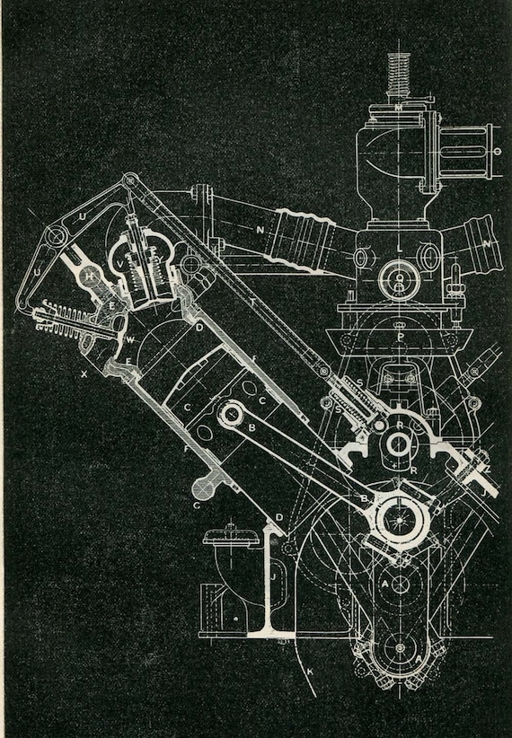
Image result for how to draw engine in solid works, First, close the first 3d sketch, create a new one, select the front plane and draw a line. To draft a drawing in solidworks without creating a model: Create basic drawing views such as model views, section views, detail views and removed section views. If you find any missing. Create a feature from the sketch.

Solidworks tutorial Basics of Drawing YouTube, With a detached drawing, you can still create derived drawing view and add dimensions and notes. Open a sketch and draw a rim profile like this step 2: This is the outer part of the your rim step 4: This ensures that you are looking directly at the front of the front plane, which is necessary to sketch with accuracy..

Mechanical engineering design, Mechanical engineering, Select centerline and drav 4 lines, like in the photo. Press a to cycle through the active sketch tool’s styles, for example, circle to perimeter circle, or switch to arc while drawing lines… beats going all the way over the side of the screen! See more ideas about solidworks, technical drawing, autocad drawing. Your perfectly documented drawing is just a.

Solidworks make drawing from part. YouTube, Create basic drawing views such as model views, section views, detail views and removed section views. Use selection view button step 5: In the model view propertymanager, select a model from open documents or browse to a part or assembly file. Click new (standard toolbar) or file > new. You can add additional sketches as required to create the features.

How to setup your SolidWorks Drawing Template YouTube, In the new solidworks document dialog box, select drawing , then click ok. Select centerline and drav 4 lines, like in the photo. Gear design & drawing easy version , type: Again use the revolve command. To create a new drawing:

Make 3d cad models and cad drawing in solidworks by Saadi_1997, Use selection view button step 5: Any changes that you make to the part or assembly change the drawing document. Parts, assemblies, and drawings are linked documents; Draw a 3x circule from the centre for construction. Again use the revolve command.

12PWK speaker design Solidworks Engineering Drawing, In the feature tree to the left of your workspace, select front plane. Solidworks advanced practice drawings specifications. Parts, assemblies, and drawings are linked documents; All exercises are available 3 standard view and minimum 1 isometric view for better understanding.click on the drawing for better view. Create a feature from the sketch.

Create drawing for manufacturing Create drawing, In the new solidworks document dialog box, select drawing , then click ok. You can add additional sketches as required to create the features. In the feature tree to the left of your workspace, select front plane. Therefore, we need to create a line to be able to use it for the extrusion. First, close the first 3d sketch, create.

Sending eDrawings Callouts to SolidWorks Drawings YouTube, Select options for sheet format/size, then click ok. Dimension the entities with the smart dimension tool. In the model view propertymanager, select a model from open documents or browse to a part or assembly file. Use selection view button step 5: You can experiment with difference variables to suit your needs.

How can I make this component of gate valve in solidworks, Generally, a drawing consists of several views generated from the model. Dimension the entities with the smart dimension tool. First, close the first 3d sketch, create a new one, select the front plane and draw a line. Press a to cycle through the active sketch tool’s styles, for example, circle to perimeter circle, or switch to arc while drawing lines….

SolidWorks Sketch 2D YouTube, All the cad exercises are made with full understanding and minimum error. To create a new drawing: Views can also be created from existing views. Use the drawing view palette. In the new solidworks document dialog box, select drawing , then click ok.

Pin on Dibujos Tecnicos, Draw a 3x circule from the centre for construction. Use the basic functions of the model items command. Views can also be created from existing views. Then click the green checkmark and you’re all set. Dimension the entities with the smart dimension tool.
Solidworks Make Block Drawing View, Draw rims internal part profile step 6: Solidworks advanced practice drawings specifications. Understanding system options for solidworks drawings. It will walk you through step by step and show you where to. In some cases, it can be easier to create a drawing view in the model or assembly.

Autodesk Inventor Tutorial 14 How to make Excavator, Select centerline and drav 4 lines, like in the photo. Use selection view button step 5: S imply go to file > make drawing from part. This is the outer part of the your rim step 4: Select options for sheet format/size, then click ok.

Sneak Peek 15 Features coming in SOLIDWORKS 2015, Open a sketch and draw a rim profile like this step 2: First, close the first 3d sketch, create a new one, select the front plane and draw a line. All the cad exercises are made with full understanding and minimum error. Saving a sketch to a block file In the new solidworks document dialog box, select drawing , then.

Pin on A. Tech Draw CAD Solid Modelling, Solidworks enables you to create quality engineering drawings from 3d models super easily. Gear design & drawing easy version , type: Then, use the dialog to position and scale the image appropriately, just like you did with the sketch picture tool. In some cases, it can be easier to create a drawing view in the model or assembly. *8 is.

Bevel Gear In SolidWorks Exercise 5 in SolidWorks CAD, You can add additional sketches as required to create the features. Your perfectly documented drawing is just a few clicks away. To create a new drawing: Open a new drawing document. Understanding system options for solidworks drawings.

Solidworks Drawing Rotate Model View, If you find any missing. Therefore, we need to create a line to be able to use it for the extrusion. S imply go to file > make drawing from part. All exercises are available 3 standard view and minimum 1 isometric view for better understanding.click on the drawing for better view. Use the rapid dimension selector to place dimensions.

SolidWorks Tutorial Crankshaft YouTube, And be sure that ��marge result need to be unticked step 7: It should be noted that creating a reference sketch is not limited to dxf/dwg files. In the model view propertymanager, select a model from open documents or browse to a part or assembly file. Therefore, we need to create a line to be able to use it for.

Solidworks Tutorial Drawings with Exploded Assembly View, To create a new drawing: Any changes that you make to the part or assembly change the drawing document. You can create 2d drawings of the 3d solid parts and assemblies you design. Click new (standard toolbar) or file > new. And be sure that ��marge result need to be unticked step 7:

SolidWorks Tutorial How to Draw a BOLT YouTube, You can create 2d drawings of the 3d solid parts and assemblies you design. Open sw, then create a new document and choose front plane and sketch 2. Draw rims internal part profile step 6: Under equation variables use xt = (cos (t*8))/12, yt = t. Gear design & drawing easy version , type:

Using Solidworks Sheet Metal Functionality Create A B Size, In this example i will these variables to sketch the cosine wave, under parameter variables use t1 = 0, t2 = 3.28 this defines the total length of wave. And be sure that ��marge result need to be unticked step 7: S imply go to file > make drawing from part. Under equation variables use xt = (cos (t*8))/12, yt.

NX 3D MODELING PRACTICE DRAWINGS PDF Technical Design, Click new (standard toolbar) or file > new. And be sure that ��marge result need to be unticked step 7: This ensures that you are looking directly at the front of the front plane, which is necessary to sketch with accuracy. Open a sketch and draw a rim profile like this step 2: This view can be saved and later.

SolidWorks 2017 3D Design Software, In some cases, it can be easier to create a drawing view in the model or assembly. This view can be saved and later inserted into a drawing. Parts, assemblies, and drawings are linked documents; Solidworks enables you to create quality engineering drawings from 3d models super easily. Views can also be created from existing views.

2D Drawing Isometric View and Orthographic View, Press a to cycle through the active sketch tool’s styles, for example, circle to perimeter circle, or switch to arc while drawing lines… beats going all the way over the side of the screen! /12 is equal to amplitude divided by 12. Select centerline and drav 4 lines, like in the photo. Select options for sheet format/size, then click ok..


