Draw a horizontal line segment from dc. Click on the transfer function in the table below to jump to that example.
Draw The Straight Line Approximation And Sketch The Bode, L l l l ( 1)( 1) ( 1)( 1) ( ) 1 2 1 2 1 2 1 2 + + + + = p s p p p s z s z kz z s h s where k, z 1, z 2, etc are all constant values. Draw a horizontal line segment from dc. Here, we refer to the z variables as zeros and the p variables as poles, and a may be a function of w.
 Bode Plots For The Frequency")
As originally conceived by hendrik wade bode in the 1930s, the plot is an asymptotic. This method involves looking at the transfer function and reducing it to roots in the numerator and denominator. The 2nd graph should be drawn using matlab. It also goes through 20 db at 0.1 rad/sec,.
Solved Draw (straight Line) Bode Plots For The Frequency from Sketchart and Viral Category
Use graph paper and a straight edge. Draw a horizontal line segment from dc. (note that a decade is a multiple of 10 1,10,100,1000,etc) 1. The phase plot has a constant 90. Accurately draw it on the graph provided. Examples (click on transfer function) 1.

Solved Problem 1 Draw Bode Diagram With Straight Line A, Also shown is a zero reference line. (real poles and zeros) 3. Draw a horizontal line segment from dc. +s10)� g) g+10 (s2 +0.1s+ 1)2. Example 1 draw the bode diagram for the transfer function:

- Draw the straight line approximation of the Bode, J.f 15.hz 2 20.hz j.f 1000 4.j.f you must show and use the method from the class notes to get the bode plot. The entire bode log magnitude plot is the result of the superposition of all the straight line terms. Rearrange the equation into standard form: Connect lines at ω 0. This means with a little practice, we can.
")
Bode Plots (example 4), I found a script in matlab central, i didn�t try it but maybe it is enough for you. Rearrange the equation into standard form: Each of these individual terms is very easy to show on a logarithmic plot. (note that a decade is a multiple of 10 1,10,100,1000,etc) 1. Show exact bode plot (and a time domain example) exact plot.

16.1 For the following systems, sketch the Bode diagram, It is usually a combination of a bode magnitude plot, expressing the magnitude of the frequency response, and a bode phase plot, expressing the phase shift. +s10)� g) g+10 (s2 +0.1s+ 1)2. The pink dots show the magnitude and phase of the bode plot at a frequency chosen by the user (see below). The entire bode log magnitude plot is.
")
Bode Plots (example 3), Draw high frequency asymptote at +20 db/decade; +s10)� g) g+10 (s2 +0.1s+ 1)2. Show exact bode plot (and a time domain example) exact plot. Here, we refer to the z variables as zeros and the p variables as poles, and a may be a function of w. The phase plot has a.

- Draw The Straight Line Approximations Of The, Bode sketching rules (gain) • start by sketching the asymptotes: In this case there is no need for approximate functions and asymptotes, we can plot the exact funtion. Each of these individual terms is very easy to show on a logarithmic plot. Compute the poles and zeros of the transfer function. On the bode plot, the gray lines represent the.
 Find The Transfer Function Corresponding To Th")
Solved (A) Find The Transfer Function Corresponding To Th, +s10)� g) g+10 (s2 +0.1s+ 1)2. Find the poles and zeros write the transfer function of the circuit in the form h(jw) = a(w) 1 + jw z 1 1 + jw z2 1 + jw p 1 1 + jw p2 and identify the location of the zeros and poles. Plot the bode plots of (1) in matlab. It.
 Bode Plots For The Frequency")
Solved Draw (straight Line) Bode Plots For The Frequency, Clearly the uncorrected plot captures the essential behavior of the frequency response with a minimum of effort. Also shown is a zero reference line. If you need more accuracy in this range you could start the plot at 90 degrees at a lower frequency and draw a smooth fit line. It is usually a combination of a bode magnitude plot,.
")
Bode Plots (example 4), Plot the bode plots of (1) in matlab. Separate the transfer function into its constituent parts. The 1st graph should be drawn on a picture using straight line. It is convenient and useful to show the properties of the transfer function using graphs of the magnitude (or gain) and phase as a function of frequency. (note that a decade is.
 Sketch the approximate straightline… bartleby")
Answered 1) Sketch the approximate straightline… bartleby, Click on the transfer function in the table below to jump to that example. Connect lines at ω 0. That is, show things like the corner You must show and use the method from the class notes to get the bode plot. A list of the systems in the user workspace.
 Bode Plot Fo")
Solved Sketch The Asymptotic (straight Line) Bode Plot Fo, What you want is called asymptotic bode diagram. It also goes through 20 db at 0.1 rad/sec,. An approximate technique for constructing a gain bode plot is shown in figure 10.10 the method for bode graph straight line gain approximation. Click on the transfer function in the table below to jump to that example. You must show and use the.
 Find The Transfer Function Cor")
Solved 2. Bode Diagram (A) Find The Transfer Function Cor, View draw bode plots from elen 90055 at university of melbourne. Matlab does not sketch the bode plot, it evaluates the transfer function at various frequencies and draw modulus and phase on the two diagrams. Draw high frequency asymptote at +20 db/decade; Within this frequency range, the slopes of both factors are combined (and in this case cancel each other.

Solved Draw The Straightline Approximation Of The Bode P, By inspection, it is 1, or 0db. Determine the poles and zeros. Each of these individual terms is very easy to show on a logarithmic plot. Identify the transfer function written in time constant form. Plot the bode plots of (1) in matlab.

Solved Draw The Asymptotic Bode Plot (the Straightline A, The phase plot has a. Plot the bode plots of (1) in matlab. (note that a decade is a multiple of 10 1,10,100,1000,etc) 1. Accurately draw it on the graph provided. Identify the transfer function written in time constant form.

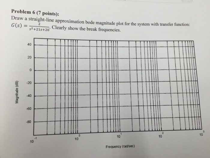
Draw a straightline approximation bode magnitude, The phase plot has a constant 90. It is convenient and useful to show the properties of the transfer function using graphs of the magnitude (or gain) and phase as a function of frequency. The phase plot has a. (real poles and zeros) 3. The 1st graph should be drawn on a picture using straight line.

The Asymptotic Bode Diagram Erik Cheever, A list of the systems in the user workspace. I found a script in matlab central, i didn�t try it but maybe it is enough for you. Draw the straight line approximations of the magnitude and phase bode plots of the transfer function. Click on the transfer function in the table below to jump to that example. Now, using the.

Electrical Engineering Archive May 23, 2017, On the bode plot, the gray lines represent the asymptotic plot, adn the black line is the exact solution. To do this we have to understand the effect of the J.f 15.hz 2 20.hz j.f 1000 4.j.f you must show and use the method from the class notes to get the bode plot. It is usually a combination of a.
")
Bode Plots (example 2), Also shown is a zero reference line. Compute the poles and zeros of the transfer function. Notice how the imparted slope values for the individual factors have ranges that overlap. Identify the transfer function written in time constant form. (note that a decade is a multiple of 10 1,10,100,1000,etc) 1.

Solved Problem 1 Draw Bode Diagram With Straight Line A, Each of these individual terms is very easy to show on a logarithmic plot. The numerator is an order 0 polynomial, the denominator is order 1. Now, using the magnitude and phase angle analysis, we need to construct the bode plot. +s10)� g) g+10 (s2 +0.1s+ 1)2. As originally conceived by hendrik wade bode in the 1930s, the plot is.

System Dynamics and Control Module 20 How to Sketch, Plot the bode plots of (1) in matlab. Accurately draw it on the graph provided. Draw the straight line approximations of the magnitude and phase bode plots of the transfer function. Now, using the magnitude and phase angle analysis, we need to construct the bode plot. 8 rows draw low frequency asymptote at 0 db;

How can a Bode plot be like that? Electrical Engineering, On the bode plot, the gray lines represent the asymptotic plot, adn the black line is the exact solution. On a sheet of paper, draw the axes for the logarithmic magnitude (a in db, linear scale—note that this is equivalent to the magnitude m drawn in logarithmic scale) over the frequency ω, logarithmic scale.underneath, draw the axes for the. A.

16.1 For the following systems, sketch the Bode diagram, The pink dots show the magnitude and phase of the bode plot at a frequency chosen by the user (see below). This is generally done by plotting the magnitude in db and the phase in degrees, as a function of the log of the frequency; Draw high frequency asymptote at +20 db/decade; Clearly the uncorrected plot captures the essential behavior.

16.1 For the following systems, sketch the Bode diagram, That is, show things like the corner frequency(ies) , the approximations of the transfer function Each of these individual terms is very easy to show on a logarithmic plot. It is usually a combination of a bode magnitude plot, expressing the magnitude of the frequency response, and a bode phase plot, expressing the phase shift. The 1st graph should be.

Solved Sketch The Bode Straight Line Plots For Magnitude, Rewrite the transfer function in proper form. Click on the transfer function in the table below to jump to that example. Matlab does not sketch the bode plot, it evaluates the transfer function at various frequencies and draw modulus and phase on the two diagrams. (b) g = (s +1)(s +10) (s+1)(s+10); +s10)� g) g+10 (s2 +0.1s+ 1)2.
")
Bode Plots (example 2), The phase plot has a. Here, we refer to the z variables as zeros and the p variables as poles, and a may be a function of w. Accurately draw it on the graph provided. 8 rows draw low frequency asymptote at 0 db; In this case there is no need for approximate functions and asymptotes, we can plot the.