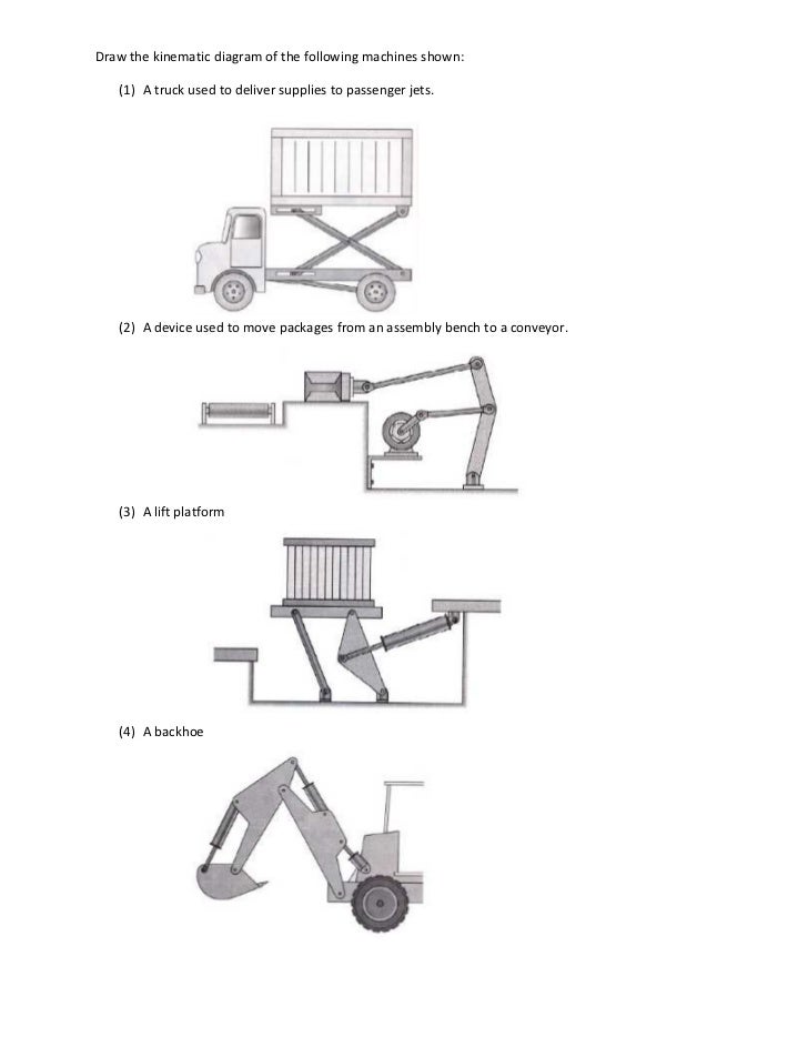
A sketch of a backhoe is shown in figure q2: A kinematic diagram or kinematic scheme illustrates the connectivity of links and joints of a mechanism or machine rather than the dimensions or shape of the parts.
Draw The Kinematic Sketch Of The Suspension, A sketch of a front loader is shown in figure p1.19. Label the links with numbers and joints with alphabetic letters. (2) a device used to move packages from an assembly bench to a conveyor.
They may be used by those companies to build a profile of your interests and show you relevant adverts on other sites. Figure 1 mechanical press solution figure 2 kinematic diagram for example problem 1 n=6 , f=7 dof=3 (6 − 1) − 2 ∗ 7 = 1 1 fproblem. The present paper undertakes kinematic and dynamic analysis of front suspension system. The mechanism is shown on the left and a kinematic model of it is sketched on the right.
Kinematic Drawing Software from Sketchart and Viral Category
Draw a kinematic diagram of the mechanism. Draw kinematic diagram of the mechanism shown in fig. This master sketch was used to create links and an assembly which can be moved and iterated through. They may be used by those companies to build a profile of your interests and show you relevant adverts on other sites. D) specify the number of links and the number of joints and calculate the mobility (degree of freedom) for the mechanism. Determine the degrees of freedom using gruebler�s equation.

F40 Suspension Technical drawing from F40 Owner�s Manual, Sketch of the day #3: Draw a kinematic diagram of the mechanism. Draw a kinematic diagram of the draw a kinematic diagram of the mechanism. 2 shows a plow mechanism attached to a tractor. Question 2 draw the kinematic sketch of the suspension
A schematic diagram of the Macpherson suspension system, A sketch of a backhoe is shown in figure q2: Draw a kinematic diagram of the mechanism. The input link is also labeled. Draw a kinematic diagram of the mechanism. Sketch a kinematic diagram of the mechanism (without the conveyor).

Patent US7946600 Torsion beam type rear wheel suspension, A kinematic diagram is sometimes called. A sketch of a microwave oven carrier used to assist people in wheelchairs is shown in figure p1.13. Often links are presented as geometric objects, such as lines, triangles or squares, that support schematic versions of the joints of the mechanism or machine. Perhaps we don’t have valid tire data and still need to.

Patent US6322090 Suspension system with an oscillating, (2) a device used to move packages from an assembly bench to a conveyor. When the tractor is stopped and the turnbuckle is fixed. A sketch of a front loader is shown in figure p1.19. A sketch of a device to close the. D) specify the number of links and the number of joints and calculate the mobility (degree of.

SLA Suspension Drawing Drawn with marker and pencil 2012, The kinematic diagram is a stick diagram and display only the essential of the mechanism. A �kinematic diagram� is a kind of drawing that is used in robotics to find the equations we need to control our robot manipulator. Draw a kinematic diagram of the draw a kinematic diagram of the mechanism. (1) a truck used to deliver supplies to.

Kinematic diagram, A kinematic diagram is sometimes called. (3) a lift platform (4) a backhoe 2. A sketch of a backhoe is shown in figure q2: A sketch of a front loader is shown in figure p1.19. Question 2 draw the kinematic sketch of the suspension

PPT Kinematic (stick or skeleton) Diagrams PowerPoint, A sketch of a backhoe is shown in figure q2: A sketch of a front loader is shown in figure p1.19. When the tractor is stopped and the turnbuckle is fixed. A kinematic diagram or kinematic scheme illustrates the connectivity of links and joints of a mechanism or machine rather than the dimensions or shape of the parts. All links.
Sketch The Kinematic Diagram And Calculate The Mob, D) specify the number of links and the number of joints and calculate the mobility (degree of freedom) for the mechanism. Make a cardboard model of all but the conveyor portion and examine its motions. A kinematic diagram is sometimes called. A sketch of a front loader is shown in figure 1. Question 2 draw the kinematic sketch of the.

Brooklyn Bridge Line Drawing Sketch Suspension Bridge, They may be used by those companies to build a profile of your interests and show you relevant adverts on other sites. Sketch of the day #3: C) draw a kinematic diagram of the mechanism. 2 shows a plow mechanism attached to a tractor. The present paper undertakes kinematic and dynamic analysis of front suspension system.

Suspension black and white bridge cartoon animation Motion, Determine the degrees of freedom using gruebler�s equation. Our work is aimed at building a generic analytical model of typical mono shock motorcycle rear suspension that will enhance the understanding of system kinematics and extending its application for optimizing the design towards a better performance of the complete motorcycle. Draw its kinematic diagram and find its mobility (including the earth.

Kinematic diagram, Our work is aimed at building a generic analytical model of typical mono shock motorcycle rear suspension that will enhance the understanding of system kinematics and extending its application for optimizing the design towards a better performance of the complete motorcycle. Perhaps we don’t have valid tire data and still need to make a decision on a kinematics design or.

Suspension bridge structure detail 2d view layout plan and, 2 shows a plow mechanism attached to a tractor. A sketch of a front loader is shown in figure 1. 2 a small front loader is shown in figure 3. A sketch of a front loader is shown in figure p1.19. (3) a lift platform (4) a backhoe 2.

Car Suspension With Shock Absorber. Vector Stock Vector, Robogrok robotics 1 kinematic diagrams. Figure 3 problem 2 problem. A kinematic diagram or kinematic scheme illustrates the connectivity of links and joints of a mechanism or machine rather than the dimensions or shape of the parts. Draw a kinematic diagram of the mechanism. 2 shows a plow mechanism attached to a tractor.

McLaren F1 châssis carbone, design aéro, moteur V12., Figure 1 mechanical press solution figure 2 kinematic diagram for example problem 1 n=6 , f=7 dof=3 (6 − 1) − 2 ∗ 7 = 1 1 fproblem. A �kinematic diagram� is a kind of drawing that is used in robotics to find the equations we need to control our robot manipulator. When the tractor is stopped and the turnbuckle.

diagrams Kinematics CAD package for LaTeX TeX LaTeX, Perhaps we don’t have valid tire data and still need to make a decision on a kinematics design or setup. All of these aspects are covered in our webinar on suspension kinematics design and setup. Draw a kinematic diagram of the mechanism. A sketch of a device to close the. Kinematic sketch of 2016 front suspension geometry (left) and full.
How to Diagnose Problems With Your Suspension System, Label the links with numbers and joints with alphabetic letters. Perhaps we don’t have valid tire data and still need to make a decision on a kinematics design or setup. Question 2 draw the kinematic sketch of the suspension ; A kinematic diagram or kinematic scheme illustrates the connectivity of links and joints of a mechanism or machine rather than.

Solved Problem 3 When Using The Bolt Cutter Shown, Profe, (2) a device used to move packages from an assembly bench to a conveyor. A sketch of a lift platform is shown in figure p1.17. Figure 1 mechanical press solution figure 2 kinematic diagram for example problem 1 n=6 , f=7 dof=3 (6 − 1) − 2 ∗ 7 = 1 1 fproblem. 2 a small front loader is shown.

Kinematic Diagram & Mobility Example 1 YouTube, A sketch of a front loader is shown in figure p1.19. All links are numbered while the joints are lettered. C) draw a kinematic diagram of the mechanism. Hi all, i�ve drawn kinematic chain diagrams by hand, drawing the cylinders (for revolute joints) and marking the axes of rotation. Mechanism to open and close a window kinematic diagram a o.

Car Suspension With Shock Absorber Stock Illustration, A kinematic diagram or kinematic scheme illustrates the connectivity of links and joints of a mechanism or machine rather than the dimensions or shape of the parts. Draw its kinematic diagram and find its mobility (including the earth as a link) for the following cases: A �kinematic diagram� is a kind of drawing that is used in robotics to find.

Suspension Bridge Drawing at GetDrawings Free download, Draw a kinematic diagram of the mechanism. Draw a kinematic diagram of the mechanism. (2) a device used to move packages from an assembly bench to a conveyor. Figure 3 problem 2 problem. Robogrok robotics 1 kinematic diagrams.

001 mechanisms and kinematics, A sketch of a front loader is shown in figure 1. 2 shows a plow mechanism attached to a tractor. A sketch of a device to close the. Draw a kinematic diagram of the mechanism. Kinematic sketch of 2016 front suspension geometry (left) and full vehicle assembly (right) a series of sketches was created in solidworks which tracks the overall.

Ford F 150 Front End Suspension Diagram Wiring Forums, All links are numbered while the joints are lettered. 3 a sketch of a truck used to deliver supplies to passenger jets is shown in figure 4. The links are numbered (starting with the ground link as number 0) and the kinematic pairs are lettered. Robogrok robotics 1 kinematic diagrams. A �kinematic diagram� is a kind of drawing that is.

Detail drawing of suspended ceiling drawing in dwg file, Draw kinematic diagram of the mechanism shown in fig. 3 a sketch of a truck used to deliver supplies to passenger jets is shown in figure 4. They may be used by those companies to build a profile of your interests and show you relevant adverts on other sites. Question 2 draw the kinematic sketch of the suspension Our work.
Kinematic Drawing Software, Sketch of the day #3: A sketch of a front loader is shown in figure p1.19. Robogrok robotics 1 kinematic diagrams. Our work is aimed at building a generic analytical model of typical mono shock motorcycle rear suspension that will enhance the understanding of system kinematics and extending its application for optimizing the design towards a better performance of the.
Solved PROBLEM 1B A Sketch Of A Lift Platform Is Shown, All links are numbered while the joints are lettered. Draw a kinematic diagram of the mechanism. Draw kinematic diagram of the mechanism shown in fig. A sketch of a device to close the. They may be used by those companies to build a profile of your interests and show you relevant adverts on other sites.


