It is used for daily communication in the engineering world as drawing is the international language of engineering. 670 650 10 4 holes, dia 10 web 10 35 14 15 30 50 80 18/8 60 90 120.
Draw The Free Hand Sketch Of Transformer And Sectional View, It is used for daily communication in the engineering world as drawing is the international language of engineering. 3 hours [5] [4] 109. A short summary of this paper.
Drawing the first vanishing lines 1 a i. 18.34 and draw, (i) sectional view fromthe front, (ii) view from the right and (iii) view from above.18.4.8 pressure relief valvethis valve is. Uses 3 views used to provide dimensions and special shapes by using different line types. The hole tolerance is to be 1.5 times the shaft tolerance.
Engineering Drawing Tutorials/Orthographic and sectional from Sketchart and Viral Category
(i) sectional front view along a a (ii) top view (iii) right hand side view [6] ans.: Without further ado, let’s get started with an overview of the basic shape of the hand. Create digital artwork to share online and export to popular image formats jpeg, png, svg, and pdf. Always used in an orthographic view. Do not draw the views in other ways. Full pdf package download full pdf package.

Black and white pencil drawing of electricity poles, Sectional view to complete the drawing. Other examples of sections are given in the assembly drawing of a small hand vice (see figure 1.11) and the detailed drawing of the movable jaw of the vice (see figure 1.12). This is a good section to start discussing the drawing. C) draw neat and proportionate free hand sketch of muff coupling. Draw.

How to make an orthographic drawing in Sketchup for free, Sectional view to complete the drawing. In the second and third types of drawings, the auxiliary views are projected from the top and side views. Select the basic sectional drawing layer, use the magic wand tool on the cut area and see the magic. 2 draw the full sectional front view of the following object (free hand sketch) (5 marks).

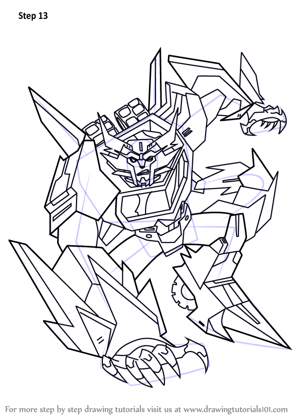
How to Draw Transformers Prime DrawingNow, It is used for daily communication in the engineering world as drawing is the international language of engineering. 2 draw the full sectional front view of the following object (free hand sketch) (5 marks) 3 a shaft and hole have a basic size of 23 mm, and are to have a clearance fit (5 with a maximum clearance of 0.02.

Building Section Drawing at GetDrawings Free download, Sectional view to complete the drawing. • show only the important dimensions on the assembly drawing. The methods are more complex and are provided at step 16 in my course learn to draw in 18 steps. Isometric view of a machine component draw its 1)fll ti lf t ifull sectional front view (sectional f.v.) 2)top view 3)l.h.s view use first.

Learn How to Draw Steeljaw from Transformers (Transformers, 7.2 draw (a) half sectional view from the front, top half in section and (b) half sectional view from the side, left half in section, of a. Turn off the dimension layer The purpose is to convey all the information necessary for manufacturing a product or a part. Draw the 2d sketch as shown 3. When viewing the elevatio n.

Drawings for the Electric Power Field, Engineering drawings use standardised language and symbols. Draw tangent and normal at any point on the curve. Here is a front view auxiliary of a simple object with an inclined surface. When viewing the elevatio n from the left hand side, then the e nd view is drawn on the right hand side of the elevation (vii) it is the.

Graphics Archives Avoid Obvious Architects, This is a good section to start discussing the drawing. When sketching an object or part that requires a sectional view, they are drawn by eye at an angle of approximately 45 degrees, and are spaced about 1/8” apart. (viii) draw in short dashed lines to represent those hidden outlines and edges. A short summary of this paper. Always used.

Engineering Drawing, Drawing the first vanishing lines 1 a i. Sectional view to complete the drawing. When viewing the elevatio n from the left hand side, then the e nd view is drawn on the right hand side of the elevation (vii) it is the principle of first angle orthographic projection to position the views in a fixed pattern. Isometric view of.

Engineering Drawing Tutorials/Orthographic and sectional, Do not draw the views in other ways. (i) sectional front view along a a (ii) top view (iii) right hand side view [6] ans.: Limits of partial and interrupted views and sections. Turn off the dimension layer 7.2 draw (a) half sectional view from the front, top half in section and (b) half sectional view from the side, left.

Pin on Container house, D)draw the conventional representation of following welded joint— i) square butt ii)all round fillet weld. When sketching an object or part that requires a sectional view, they are drawn by eye at an angle of approximately 45 degrees, and are spaced about 1/8” apart. Q.5(b) figure shows front view and top views of an object. Draw tangent and normal at.

Engineering Drawing Tutorials/Orthographic drawing 1 with, Always used in an orthographic view. For example object, hidden, and center lines. Indicating proportions for connecting two shafts, each of diameter 30 mm. Here is a front view auxiliary of a simple object with an inclined surface. Draw the front first, top second, and right side last space the views out equally at 40 mm a miter line is.

Design of impeller for centrifugal Pump GrabCAD Tutorials, It is used when free hand lines are drawn by tools. Once all vanishing lines have been inserted it will be possible to outline the entire canopy on the strength of these new reference points and the estimated length and height of the canopy, which vanishes to the main point. There are three basic type of auxiliary views. It is.

Pin on Architecture & Paradise, Other examples of sections are given in the assembly drawing of a small hand vice (see figure 1.11) and the detailed drawing of the movable jaw of the vice (see figure 1.12). In the second and third types of drawings, the auxiliary views are projected from the top and side views. 25 full pdfs related to this paper. Transformers 3d.

Engineering Drawing Tutorials/Isometric drawing with front, Since they are used to set off a section, they must be drawn with care. Free online drawing application for all ages. 2 draw the full sectional front view of the following object (free hand sketch) (5 marks) 3 a shaft and hole have a basic size of 23 mm, and are to have a clearance fit (5 with a.

A section detail of transformer layout and foundation of, Copy view to be cross sectioned start the process by copying the front view (third angle projection) of the object. Drawing the first vanishing lines 1 a i. Do not draw the views in other ways. The next step is to indicate the vanishing lines to the main point. Draw the following views by using first angle method of projection.

Pencil to Paper A Connection to Site Olander Garden Design, (viii) draw in short dashed lines to represent those hidden outlines and edges. Draw the front first, top second, and right side last space the views out equally at 40 mm a miter line is used to project details of the object from the top view to the right side view without measuring. Q.5(c) figure shows front view and top.

» basic engineering drawing books, Parts situated in front of the cutting planes, outlines of adjacent parts, censorial lines, to state center of gravity. There, i teach how to draw hands by building a visual library. Mechanical engineering questions and answers. Draw the following views by using first angle method of projection. 105 | p a g e 3) draw the conventional representation of internal.

Highvoltage Transformer Concept Stock Vector, It is best to use the symbol for the material being shown as a section on a sketch. Other examples of sections are given in the assembly drawing of a small hand vice (see figure 1.11) and the detailed drawing of the movable jaw of the vice (see figure 1.12). 18.34 and draw, (i) sectional view fromthe front, (ii) view.

Engineering Drawing Tutorials/Orthographic drawing 2 with, Consider shape when drawing hands. B) draw neat and proportionate free hand sketch of lewis foundation bolt. Draw the 2d sketch as shown 3. Draw tangent and normal at any point on the curve. (a) draw a hypocycloid of a circle of 40 mm diameter that rolls inside another circle of 200 mm diameter for one revolution.

Engineering Drawing Tutorials / Orthographic Drawing, Consider shape when drawing hands. It is used when free hand lines are drawn by tools. A short summary of this paper. By operating the hand wheel, the spindle permits the valve to get lifted from the valve seatand allows feed water to enter the boiler.exerciseassemble the parts of the feed check valve, shown in fig. Create body of the.

Platform ladder section and structure drawing details dwg, 3 hours [5] [4] 109. D)draw the conventional representation of following welded joint— i) square butt ii)all round fillet weld. The next step is to indicate the vanishing lines to the main point. Always used in an orthographic view. Once all vanishing lines have been inserted it will be possible to outline the entire canopy on the strength of these.

Bumblebee Angry Birds Transformers Optimus Prime Colouring, Drawing the first vanishing lines 1 a i. The next step is to indicate the vanishing lines to the main point. 18.34 and draw, (i) sectional view fromthe front, (ii) view from the right and (iii) view from above.18.4.8 pressure relief valvethis valve is. It is used when free hand lines are drawn by tools. For example object, hidden, and.

Engineering Drawing Tutorials/Orthographic and sectional, Draw orthographic views of the objects shown in figure p6.3 with full sectional. It is best to use the symbol for the material being shown as a section on a sketch. Select the basic sectional drawing layer, use the magic wand tool on the cut area and see the magic. It leaves a flexibility to edit afterward without any major.

engineering graphics _ free hand sketch, Consider shape when drawing hands. A short summary of this paper. Transformers 3d models ready to view, buy, and download for free. The methods are more complex and are provided at step 16 in my course learn to draw in 18 steps. When viewing the elevatio n from the left hand side, then the e nd view is drawn on.

Site Section Drawing at GetDrawings Free download, Since they are used to set off a section, they must be drawn with care. For example object, hidden, and center lines. In the second and third types of drawings, the auxiliary views are projected from the top and side views. Indicating proportions for connecting two shafts, each of diameter 30 mm. This is a good section to start discussing.


